
A battery pack is a rechargeable battery consisting of cells connected in parallel and/or in series in combination with a battery management system. The cells and the battery management system, including all connections, are combined in a battery housing, which in the simplest case can be a shrink tube, but usually consists of a solid plastic housing.
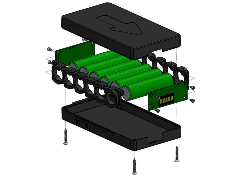
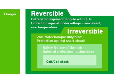
As a central element in the battery pack, the battery management system (BMS) not only monitors and regulates voltage, current and temperature, but also ensures optimum interaction between the cells. The BMS is more than just a protective circuit for the battery pack. It can also take over central functions of the end application. The safety functions of the BMS are divided into 1st level protection and 2nd level protection.
The 1st level protection is a recoverable (reversible) protection device. It monitors the voltages of the individual cells and the battery pack, the charge and discharge current and the temperature. If one of the parameters is outside the limits, the BMS prevents further charging or discharging.
In contrast to 1st level protection, 2nd level protection is irreversible: once triggered, the battery pack can no longer be used by the customer. An example of 2nd level protection is a fuse.
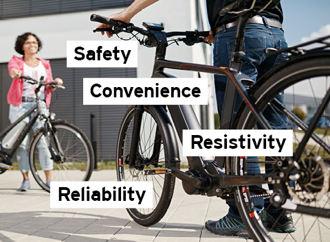
Intelligent battery management systems (BMS) offer:
Double protection by reversible and irreversible protection device, protection against harmful temperatures and implementation of functional safety.
The longevity of the product is guaranteed by the best quality of PCBs and components. In addition, Cell Balancing ensures the best capacity utilization.
The longevity of the product is guaranteed by the best quality of PCBs and components. In addition, Cell Balancing ensures the best capacity utilization.
A high-quality protective coating allows the battery to be used in harsh climates. In addition, an ESD- and EMC-compliant design ensures that the components are not damaged.
A "thermal runaway" refers to a self-reinforcing process. In this process, the decomposition reactions that begin at a certain temperature generate so much energy that, in the worst case, it leads to a violent burst. This effect cannot be stopped once it has occurred. The occurrence of a critical state, caused for example by an external short circuit or overcharging, is effectively prevented by the battery management system. But the cell itself also prevents these uncertainties through various measures:
A PTC thermistor is a heat-dependent resistor that trips when the current is too high and reversibly minimizes the current flow.
A CID causes a current-carrying bridge to deform irreversibly in the event of a misuse, so that the current flow is interrupted.
A rather new method is a fusing separator. The separator consists of two different plastics, both of which are porous. One of the two plastics melts in the event of an overtemperature and thus fills the gaps in the other plastic, which in turn leads to the current flow being minimized or coming to a standstill (shut down).
A safety valve is a predetermined breaking point which breaks open in the event of a pressure increase caused by temperature development and allows controlled blow-off of the electrolyte gas. This prevents a violent bursting.

In addition to the protection functions, other functions are possible in the BMS. These functions are not so much for safety as for optimum capacity utilization, extending service life or capacity display for the customer.
Cell Balance is used for battery packs with more than one serially connected cell in order to keep the cells or the charge states in a balanced state. In particular, Cell Balance is used to compensate for charging states caused by different temperatures and internal resistances. It prevents the battery pack from shutting down prematurely due to under- or overvoltage of a cell, whereby the weakest cell determines the performance of the overall system.
To determine the capacity of the battery pack, a BMS has a gas gauge system. The gas gauge determines the total capacity and the remaining capacity available. It is probably the most complex of the available functions. To achieve the most accurate results, it must be developed to fit the application. In particular, the current profile of the end application and the user behavior are relevant.
A BUS system is available to the battery pack for reading out the data. The most common BUS systems are I2C, SMBus, CAN, LIN or RS232, but all other buses are also possible.
For low-power systems, it may make sense to integrate the charging part for the battery pack on the BMS. This has the advantage that the charger can be adapted in the event of a cell change, thus always ensuring backward compatibility with older systems.
In systems where the battery is the central element, system functions can be relocated to the battery. This can save a second intelligence (microcontroller) in the system. For example, motor control and battery protection circuitry are combined in the battery. This saves the control microcontroller (μC) and the double design of the power FETs (FET = field effect transistors).

Various approvals and standards are possible for lithium-based battery systems, which may be relevant depending on the application and sales areas.
All lithium-based battery packs must be qualified in the UN transport test to obtain approval for transport by road, rail, inland/ocean shipping and air. Battery packs with capacities no greater than 100 Wh can be transported more easily after passing the UN test. Battery packs above 100 Wh are always shipped as class 9 dangerous goods. The UN test includes vibration, shock, temperature change, altitude simulation, short circuit and overcharge. Without passing the UN test, transport is not allowed. The only exception: During the evaluation, up to 100 battery packs can be transported as dangerous goods in a wooden crate for test purposes. A UN approval must be available if more than 100 battery packs are shipped or battery packs are shipped to the end customer. The approval is issued to the product and the production facility. Eight samples are required for this test.
Approval IEC 62133 is an international standard for portable rechargeable batteries. Approval with CB Report is not mandatory unless explicitly required by a device standard. Many other standards (e.g. 60601 Medical) require IEC 62133 approval for battery packs. 13 samples are required for this test.
UL62133 is the North American harmonization of IEC 62133 and is of interest to anyone planning a market launch in North America. With the approval according to UL 62133, the CB Report for IEC 62133 can also be obtained. If approved by Underwriters Laboratories (UL), a quarterly manufacturing inspection is required to maintain the certificate. In addition, a sample must be sent to UL annually for requalification. 25 samples are required for this test.
UL 2054 was the only option for UL approval of batteries before the harmonization of IEC 62133. It differs primarily in that tests are also carried out on battery packs with a built-in first fault, which significantly increases the time and financial outlay. A first fault is, for example, a bridged protective FET. Approximately 55 samples are required for this test.
We implement Functional Safety in accordance with IEC 61508 and its application-specific daughter standards (including ISO 13849 for machinery / equipment, ISO26262 for automobiles and motorcycles). The implementation of functional safety serves as proof of development in accordance with the current state of the art in product liability cases pursuant to the German Product Liability Act (ProdHaftG). Implementation begins with the identification and quantification of potential risks due to malfunctions of the system under consideration. Based on the potential risk, technical and methodical measures are implemented in the development to provide proof of functional safety.

As your electronics partner, we offer you an all-round package. From consulting to development to series production, on the way to a successful product we support you flexibly and competently. All information about our services as your project partner can be found here:

In a nutshell: founded 1989, 140 employees, manufacturer of intelligent electronics.
FSM AG
Erich-Rieder-Strasse 2
D-79199 Kirchzarten
Telefone +49 7661 9855 0
E-Mail info@fsm.ag
Please feel free to contact us!